| Uploader: | Kazijind |
| Date Added: | 17 September 2011 |
| File Size: | 41.78 Mb |
| Operating Systems: | Windows NT/2000/XP/2003/2003/7/8/10 MacOS 10/X |
| Downloads: | 83350 |
| Price: | Free* [*Free Regsitration Required] |
Some slave dwvice are designed to devce any SPI communications in which the number of clock pulses is greater than specified. That's for an unknown kernel on an AT91 processor, and only deals with I2C communcation with the CS control port. Chip, chip debugging method and communication method for chip and external devices. The SPI port of each slave is designed to send out during the second group of clock pulses an exact copy of the data it received during the first group of clock pulses.
[03/46] Davinci: DM Add platform device for McBSP - Patchwork
Beagleboard Kernel Module Cross Compiling. Join our community today!

Sign in Sign in Remember me Forgot username or password? Examples include pen-down interrupts from touchscreen sensors, thermal limit alerts from temperature sensors, alarms issued by real time clock chips, SDIO[6] and headset jack insertions from the sound codec in devicr cell phone.
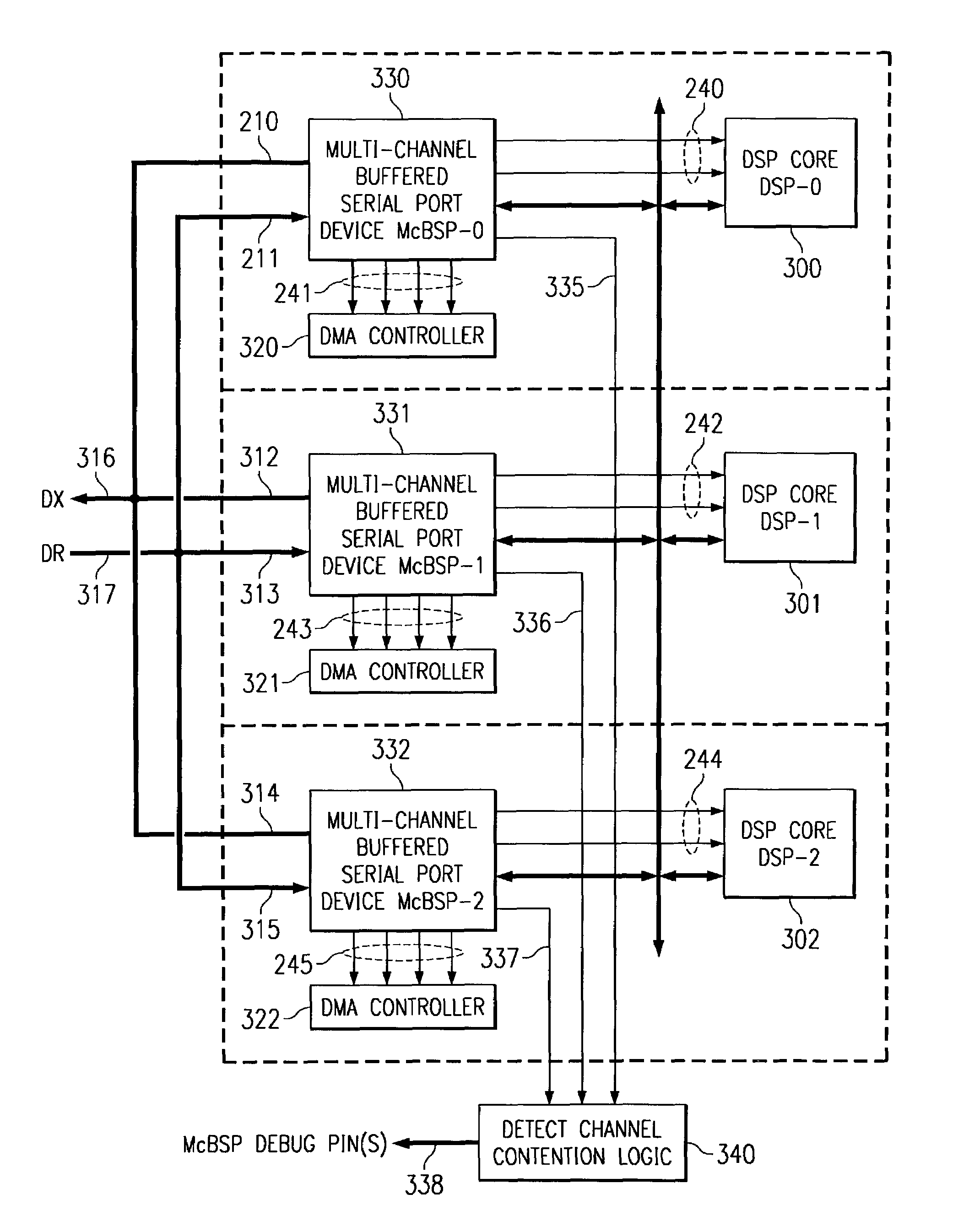
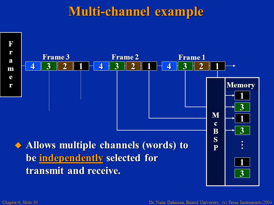
The new version presents time slot identification to DMA controller and DSP core whenever it asserts a request corresponding to either a transmit event mcbsl a receive event.
US7028118B2 - Multi-channel buffered serial port debugging - Google Patents
If a single slave device is used, the SS pin may be fixed to logic low if the slave permits it. Few SPI master controllers support this mode; although it can often be easily bit-banged in software. Originally Posted by LittleLenni. The interface was developed by Motorola in the mid s and has become a de facto standard. Logic analyzers display time-stamps of each signal level change, which can help find protocol problems.
Multithreaded microprocessor with register allocation based on number of active threads. Chip or FPGA based designs sometimes use SPI to communicate between internal components; on-chip real estate can be as costly as its on-board cousin.
I really appreciate it! Allright, thanks for your assesment. It sounds quite possible to do actually and allthough Alsa-support would be grate, it probably isn't necessary. It's related to the Gumstix, but since it's the same processor I'm sure the vast majority of it will apply to your board as well. On the next clock edge, at each receiver the bit is sampled from the transmission line and set as a new least-significant bit of the shift register. Find More Posts by suicidaleggroll.
It tends to be used for lower performance parts, such as small EEPROMs used only during system startup and certain sensors, and Microwire. Many SPI chips only support messages that are multiples of 8 bits.
I had to write a custom kernel module for the interface from scratch, since there was nothing out of the box that I could use. Did you had a look on this link http: On the clock edge, both master and slave shift out a bit and output it on the transmission line to the counterpart. SPI protocol analyzers are tools which sample an SPI bus and decode the electrical signals to provide a higher-level view of the data being transmitted on a specific bus.
Data is usually shifted out with the most-significant bit first. Multi-channel buffered serial ports also have a direct communication link with DSP core via bus and with memory via M bus During each SPI clock cycle, a full duplex data transmission occurs.

SPI master and slave devices may well sample data at different points in that half cycle. Such a ready or enable signal is often active-low, and needs to be enabled at key points such as after commands or between words. Last edited by LittleLenni; at This standard defines an Alert signal that is used by an eSPI slave to request service from the master.


No comments:
Post a Comment